Hangor 2.0 Technical Design Report
Competition strategy, vehicle specifications, mechanical improvements, software stack, testing strategy and appendices.
Download DOCX
Our Research
Download core technical documents and explore our team's design work, system diagrams and assembly videos that power Hangor's development.
Documents
Competition strategy, vehicle specifications, mechanical improvements, software stack, testing strategy and appendices.
Download DOCXElectrical reliability strategy, power distribution, kill switch architecture, rail regulation, telemetry and testing phases.
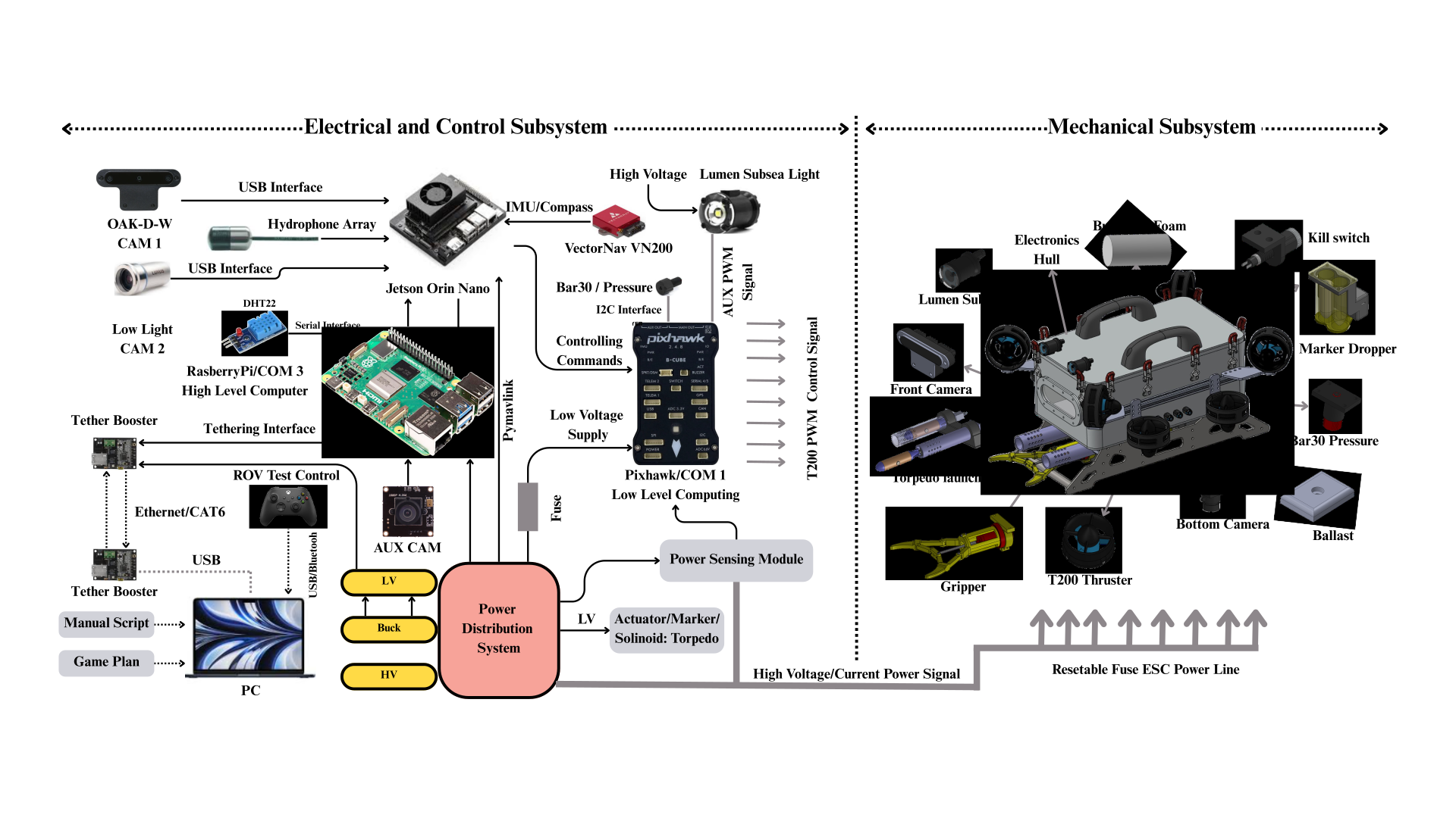
Download DOCXSystem-level architecture diagrams connecting compute, sensors, power, mechanical modules and mission hardware.
Download PDFDesign Assembly
Watch a concise assembly walkthrough showcasing Hangor 2.0's mechanical modules, connector placements and integration flow — ideal for engineers and partners.
Visual Architecture
Use these diagrams on the website to explain how the AUV connects vision, sensing, compute, power, thrusters and external tools.
Hydrodynamic Design
Hangor vehicles are designed using advanced hydrodynamic principles to minimize drag and maximize maneuverability in complex underwater environments.
The ogive nose cone geometry reduces frontal drag and improves pressure distribution across the vehicle envelope. This streamlined profile allows sustained forward speeds while maintaining directional stability in currents and confined spaces.
Comparative analysis between cylindrical, torpedo, and ogive profiles demonstrates superior efficiency of our ogive design across Reynolds number ranges relevant to AUV operation (10^5 to 10^6). Pressure recovery zones minimize flow separation and vortex-induced vibration.
Performance & Specifications
Mechanical Architecture
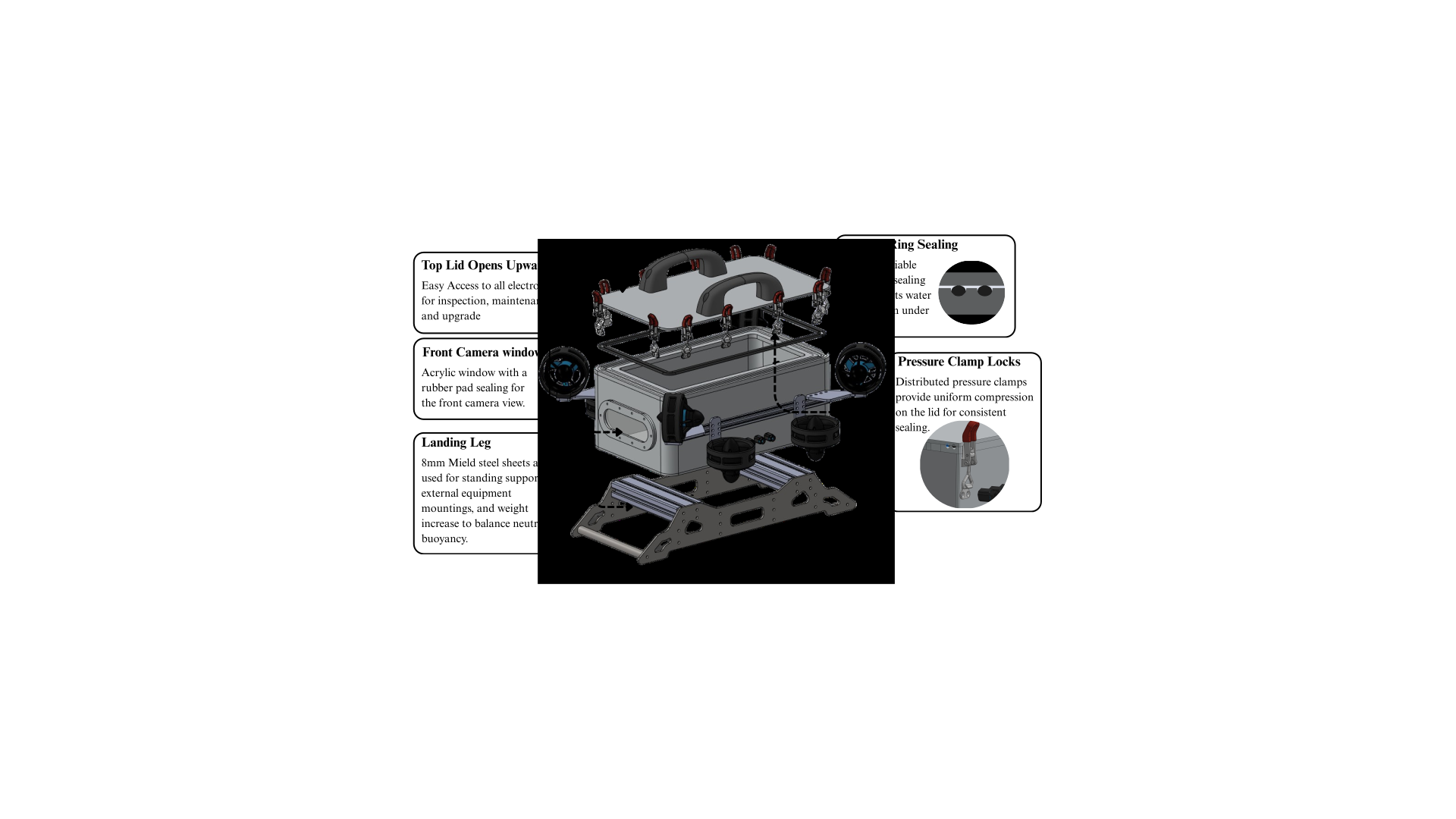
Hangor vehicles are built around a modular frame architecture that isolates mechanical, electrical, and sensor subsystems. This approach enables rapid prototyping, easier maintenance, and flexible payload integration without redesigning the core structure.
Software & Autonomy
Hangor vehicles run a modular ROS2 autonomy stack built on the Navigation2 framework, enabling waypoint following, obstacle avoidance, dynamic task prioritization, and real-time telemetry streaming.
All software changes undergo simulation-in-the-loop testing before deployment. We maintain a high-fidelity Gazebo simulation environment that models hydrodynamics, sensor noise, and communication latency.
Research Applications
Deploy to 200+ meters for coral reef mapping, fish behavior studies, and bioluminescence surveys. Custom camera payload options and stable hovering enable long observation windows.
Inspect bridge pilings, submerged pipelines, and offshore infrastructure with precision hovering and high-resolution sonar. Generate 3D point clouds and HD video for engineering review.
Map and document shipwrecks and archaeological sites. Payload-agnostic design allows integration of magnetometers, ground-penetrating sonar, and custom sampling equipment.
Autonomous sampling missions for water quality analysis, temperature profiling, and pollution source tracking. Multi-day deployments with solar charging capability.